Systems
implementation & evaluation
- What is systems implementation?
- What are the tools for physical systems design?
- What are the issues to consider before an information system is operational?
- What are the key indicators of a quality system?
- What are the techniques for systems evaluation?
Systems implementation is the process of:
- defining how the information system should be built (i.e., physical system design),
- ensuring that the information system is operational and used,
- ensuring that the information system meets quality standard (i.e., quality assurance).
Systems design
Conceptual design – what the system should do
Logical design – what the system should look to the user
Physical design – how the system should be built
Physical
system design using structured design approach:
à To produce a system that is easy to read, code, and maintain
1. Factoring: decomposition
2. Span of control: 9 subordinate modules
3. Reasonable size: 50-100 LOC
4. Coupling: minimize inter-module dependency
5. Cohesion: single module functionality
6. Shared use: multiple calls to lower level modules from different bosses
· Organization of programs and program modules (structure chart)
· Processing logic specification in each module (pseudocode)
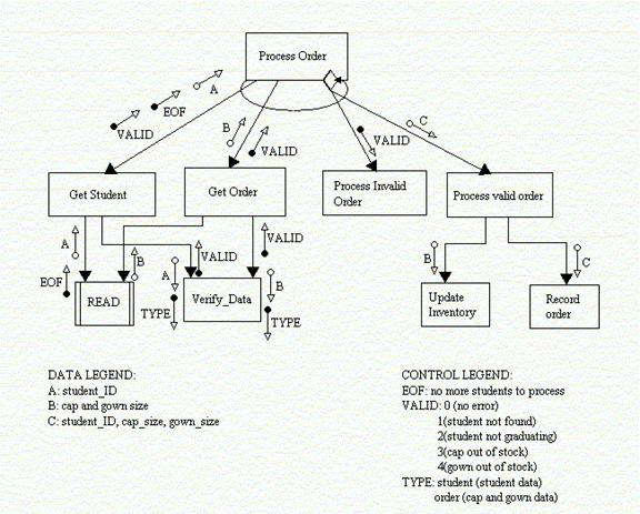
Structure chart – to show graphically
- how the various program parts/modules of an information system are physically organized hierarchically
- how the modules communicate with each other through data couple (data exchange) and flag (control/message)
- how the modules are related to each other in terms of sequence, selection, and repetition
Symbols
|
Components |
Symbol |
|
Module |
Rectangle |
|
Data couple |
Clear circle with out arrow |
|
Control flag |
Filled circle with out arrow |
|
Conditional processing/selection |
Diamond |
|
Repetition |
A curved line intersecting the connection to the modules |
|
Predefined module |
Rectangle with a vertical bar on each side |
Converting DFDs to structure charts
1. Locate the central transform/transaction center
2. Find a coordinating module for the top of the chart
3. Identify the primary input and output data flows
4. Draw a top-level chart (consists of two hierarchical level)
5. Refine the chart until the data origin, system function, and output dispositions are defined
Cap and gown ordering
system example
|
Step |
Example |
|
Center |
Process #3: Validate Order |
|
Root module |
Process Order |
|
Primary inputs |
Student ID, cap size, gown size |
|
Primary outputs |
Receipt, Order detail, Inventory update |
|
Top-level |
Get student, Get order, Process invalid order, Process valid order |
|
Refinement |
Get student, Get order, Process valid order |
Pseudocode
To provide programmers with a text description of the contents of each module
Cap and gown ordering
system example
MODULE: Process_Order()
Set EOF = no, VALID = 0
Get_Student
DO WHILE EOF = no
IF VALID = 0
Get_Order
ENDIF
IF VALID = 0
Process_Valid_Order
ELSE Process_Invalid_Order(VALID)
ENDIF
Get_Student
ENDDO
MODULE: Get_Student()
SET EOF = no, VALID = 0, TYPE="student"
READ student_ID
IF student_ID = null
THEN EOF = yes
ELSE Verify_Data(TYPE)
ENDIF
RETURN student_ID, EOF, VALID
MODULE: Get_Order()
SET TYPE = "order"
READ cap_size, gown_size
Verify_Data(TYPE)
RETURN cap_size, gown_size, VALID
MODULE: Process_Invalid_Order(valid)
IF VALID = 1
error = "Student not found"
ELSE IF VALID = 2
error = "Student is not graduating in spring"
ELSE IF VALID = 3
error = "Cap size out of stock"
ELSE IF VALID = 4
error = "Gown size out of stock"
ENDIF
ENDIF
ENDIF
ENDIF
DISPLAY error
MODULE: Verify_Data (type)
IF TYPE = "student"
THEN OPEN Student_File
FIND Student_Record USING student_ID
IF Student_Record NOT_FOUND
THEN VALID = 1
ELSE IF Student.graduate_date <> "Spring 1999"
THEN VALID = 2
ENDIF
ENDIF
ELSE IF TYPE = "order"
THEN OPEN Inventory_File
GET Inventory.cap_on_hand USING cap_size
GET Inventory.gown_on_hand USING gown_size
IF Inventory.cap_on_hand = 0
THEN VALID = 3
ELSE IF Inventory.gown_on_hand = 0
THEN VALID = 4
ENDIF
ENDIF
ENDIF
ENDIF
RETURN VALID
MODULE: Process_Valid_Order(student_ID, cap_size,
gown_size)
Update_Inventory(cap_size, gown_size)
Generate_Receipt(student_ID, cap_size, gown_size)
Record_order(student_ID, cap_size, gown_size)
MODULE: Update_Inventory(cap_size, gown_size)
OPEN Inventory_file
GET Inventory.cap_on_hand USING cap_size
REDUCE Inventory.cap_on_hand BY 1
FIND Inventory.gown_on_hand USING gown_size
REDUCE Inventory.gown_on_hand BY 1
CLOSE Inventory_File
MODULE: Record_Order(student_ID, cap_size,
gown_size)
OPEN Order_File
Order.student_ID = student_ID
Order.cap_size = cap_size
Order.gown_size = gown_size
WRITE Order_Record
PRINT Order_Record AS Receipt_Report
CLOSE Order_File
1. Testing
2. Conversion
4. Training
|
Test |
Description |
Characteristic |
|
Inspection |
Manually examine code for errors |
Detect 60 to 90 percent of defects |
|
Walkthrough (Figure 20.1) |
Manually review code to find errors by examining what the code does |
Should be done when the pieces of work are small |
|
Desk checking |
Manually work through the code, executing each instruction using test cases |
The reviewer acts as a computer |
|
Syntax checking |
Uncover syntax errors by a compiler |
The only automated testing technique that is static |
|
Unit/module testing |
Discover any error that may exist in a module's code |
Each module is tested alone |
|
Integration testing |
Discover any error that may exist by combining modules |
Top-down gradual testing |
|
System testing |
Discover any error that may exist by integrating programs into systems |
Top-down gradual testing |
Testing process (Figure 20.27)
- Program testing with test data
- Link testing with test data
- Full systems testing with test data (alpha test)
- Full systems testing with live data (beta test)
Testing guidelines
§ Test different aspects of the system, e.g., response time, response to boundary data, response to no input, response to heavy volumes of input
§ Test anything that could go wrong or be wrong about a system
§ Test the most frequently used parts of the system at a minimum
§ The people who create the test cases should not be the same people as those who coded and tested the system
§ Use debugging tools, e.g., symbolic debugger
Conversion strategies (Figure 21.12)
|
Strategy |
Pros and cons |
|
Direct/abrupt/ cold-turkey |
§ risky § least expensive |
|
Parallel |
§ less risky § expensive § confusing to users |
|
Gradual/Phased/staged |
§ more manageable § requires careful version control |
|
Modular/Pilot/single location |
§ middle-of-road approach § limits potential damage and cost |
System documentation à maintenance programmers
Records detail information about a system's design specifications, functionality (external), and internal workings (internal), e.g., DFDs, ERDs, Structured English, Structure Chart, Pseudocode.
User documentation à end-users
Records information about an application system, how it works, and how to use it, e.g., user manual, procedure manual
Documentation
standard
- Compatible
- Comprehensible
- Informative
- Adequate
- Structured
- Maintainable
Training guidelines (Figure 21.11)
- Consider who will be the trainer and trainee
- Establish measurable objectives
- Use appropriate training methods
- Select suitable training site
- Use understandable training materials
Training topics
1. Use of the system
2. Computer concepts
3. IS concepts
4. Organizational concepts
5. System management
6. System installation
Training methods
1. Local experts: 51%
2. Computer-aided instruction: 17%
3. On-line help: 10%
4. Course: 10%
5. Tutorial: 7%
6. External sources: 5%
1. Conventional wisdom: management support and user involvement
2. Factor model: Ginzberg's 4 factors, Lucas's 6 factors
Ginzberg's 4 factor model
1. Project commitment: how well understood?
2. Change commitment: how willing to change?
3. Extent of project planning and definition: how well planned?
4. User expectations: how realistic?
The Lewin/Schein change model
1. Unfreezing
· Establish a felt need
· Create a safe atmosphere
2. Moving
· Provide necessary information
· Assimilate knowledge and develop skills
3. Refreezing
· Integrate the new behavior into ongoing behavior
· Diffuse the change throughout the system
5 areas of
expectations
Goals: the reasons for developing the system
Importance: the importance of the problem being addressed
Patterns of use: the way the system will be used
Impacts: system impacts on the organization
Evaluation criteria
à discuss these expectations from time to time involving end users, mangers, and system developers
Source: Ginzberg, M.J., "Early Diagnosis of MIS Implementation Failure: Promising Results and Unanswered Questions," Management Science, vol.27, no.4, April, 1981, pp.459-478
Lucas's 6 factors model
1. User's personal stake: how important?
2. System characteristics: how easy to use?
3. User demographics: how computer literate?
4. Organization support: how committed?
5. Performance: how much can be done?
6. Satisfaction: how much is used?
|
Factor |
Description |
|
Project |
§ Setbacks are temporary § Money spent as investments toward a large pay-off § Expenditures are irretrievable |
|
Managers |
§ Reward for perseverance § See only what confirms their preferences § Self justification or protection |
|
Social pressure |
§ Do not want to admit error or expose mistakes § Associate persistence with strong leadership |
|
Organization |
§ Administrative inertia § Political resistance § Company identity |
Prevent
over-commitment
|
Means |
Description |
|
Recognize over-commitment |
§ Concrete definition of failure § Prevent personal attachment to projects § Open to other's concerns about the project § Put the company before the project § Consider withdrawal alternatives § Step back and look at the project from an outsider's perspective |
|
Change the organization |
§ Replace project managers § Separate initial from subsequent decisions § Lessen the risk of failure § Reward honest recognition of problems |
|
Experimentation attitude |
§ Avoid institutionalize projects § Subject all ventures to regular reconsideration |
Source: Staw, B.M., and Ross, J, "Knowing When to Pull the Plug," Harvard Business Review, March-April, 1987, pp.68-74
Quality
assurance – to ensure that the system actually developed meets current and
projected needs of the users and the organization
Total quality management approach to quality assurance:
- To build systems correctly from the start
- To detect and fix errors as soon as possible
Indicators of a
quality system
- Structured: top-down in design; modular in programming
- Documented
- Tested
- Maintained, and
- Audited
Structured system = structured analysis + structured design + structured programming
Structured analysis: input-process-output
Structured design: modular
Structured programming: sequence-selection-repetition
- New business/strategic development
- New technology
- Organizational changes
- Original specification is inadequate
- Government/legal changes
- External factors, e.g., suppliers, customers
- New policies, e.g., security, financial cutbacks
- Original specification is not property implemented
- Personnel changes
Source: Fitzgerald, G., Philippides,
A., and Probert, S., "Information Systems Development,
Maintenance, and Enhancement: Findings from a
- provide feedback for system improvement
- measure the success of a developed system
Evaluation technique
IS utility approach
(Figure 21.14)
An IS can be evaluated as successful if it possesses all six utilities:
- Possession (who)
- Form (what)
- Place (where)
- Time (when)
- How (actualization)
- Why (goal)