The SL_SREC dialog window opens in the top left corner of the computer screen when the user selects Experiments->SL_SREC from the main dialog window. The SL_SREC dialog window is an object of class SL_SREC (see the Classes documentation for more information) and automatically opens 2 daughter windows. The first of these (displayed in the bottom left of the screen) is an Experiment_display window. The second (in the top right) is a Calibration window. The Calibration window in turn opens its own daughter window in the bottom right of the screen, Cal_display. Thus opening the SL_SREC dialog creates 4 windows on the computer screen. You can find further information about the controls for these other windows in the appropriate documentation files.
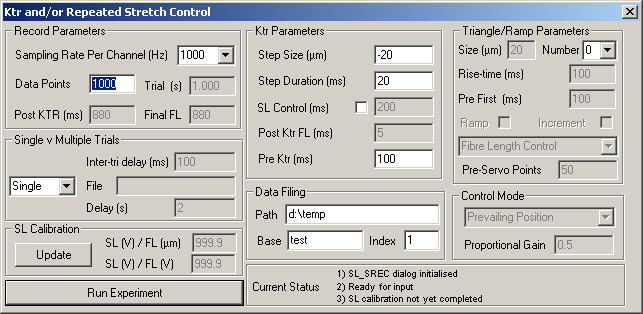
For more information about the SL_SREC_dialog controls, scroll down through this page or click on the appropriate control in the screen-shot below.
Explanation
Sampling rate per channel (Hz). User selects appropriate value from drop-down menu. Note that timing of waveforms will only be accurate to the reciprocal of the channel sampling rate. For example, if a record is digitised at 100 Hz, the timing of the output channels will only be accurate to +/- 10 ms.
The number of data points per channel.
The record duration in seconds. This number is the product of the sampling rate per channel (in Hz) and the number of data points per channel. This control is disabled. To adjust the value, the user must change either the sampling rate or the number of data points.
The time interval (ms) after the ktr step is complete
If the ktr tension recovery is recorded under sarcomere length control , the post-ktr period consists of three distinct phases. The motor is first stepped back to its default position under FL control and held at that position for a time interval specified by Post-ktr FL. The experiment then switches to sarcomere length control for the Ktr SL control period before returning to FL control for the remainder of the experiment. This control displays the time interval (in ms) of this final phase of the experiment.
SLControl checks that this value is greater than or equal to zero before running each trial. If not, SLControl aborts the trial before it is initiated and no data record is written to file. The control is always disabled. To adjust the value, the user must change at least one of the other experiment parameters. For example, if the value is negative, the user could increase the number of data points to increase the length of the trial.
The time interval (in ms) between consecutive triangles/ramp stretches. This control is only active if the user has selected the Single or Size experiment modes at which time it defines the interval (in ms) between consecutive stretches. It is disabled in Delay mode when the interval is defined in the Batch-file.
The full path for a data file containing experiment parameters for the multiple trial experimental modes (Delay and size). The control is disabled unless one of these modes is selected. The file formats for the two modes are different though each is a simple ASCII text file containing only numbers. The first number in each file is an integer (i.e. no floating point) defining the number of trials to perform. The rest of the file is a list of parameters (all floating point) for each trial. Delay trails are defined by a single value, the Inter-triangle delay. Size trials are also defined by a single value, the relative size of the first stretch. Examples of the two formats are shown below.
| Delay | Size | ||
| File | Comments | File | Comments |
| 3 100.0 10.0 1.0 |
Number of trials Inter-tri interval (ms) 100.0 Inter-tri interval (ms) 10.0 Inter-tri interval (ms) 1.0 |
3 1.0 0.5 -0.2 |
Number of trials with first stretch 1.0*Stretch-size (µm) with first stretch 0.5.0*Stretch-size (µm) with first stretch -0.2*Stretch-size (µm) |
The time interval (in seconds) between consecutive trials when the multiple trial modes (Delay and Size) are selected. The control is disabled when SLControl is in single trial mode.
Updates the sarcomere length calibration parameters with the appropriate values from the daughter Calibration window.
A SL calibration factor defined as the measured change in Sarcomere length signal for a unit change in FL_COMMAND volts. This value is derived from SL(V)/FL(µm) ratio set in the daughter Calibration window and the control is disabled at all times. To update the value, the user must first change the value in the Calibration window and then select the Update button in the Tension_control_dialog window. Although this arrangement may seem unusual, it allows the user to check the calibration factors between experiments without necessarily altering the experimental conditions for the Tension-control experiments.
A SL calibration factor defined as the measured change in sarcomere length signal for a 1 micron increase in FL_COMMAND volts. The value is set in the daughter Calibration window and the control is disabled at all times. To update the value, the user must first change the value in the Calibration window and then select the Update button in the Tension_control_dialog window. Although this arrangement may seem unusual, it allows the user to check the calibration factors between experiments without necessarily altering the experimental conditions for the Tension-control experiments.
As the label suggests, this button initiates an experiment. If the user has selected the Single mode, pressing this button will run a single trial. If the user has selected a multi-trial mode, this button will initiate a train of consecutive trials, separated in time by the Inter-trial-delay. In this case, the number of trials performed depends on the parameters set in the appropriate Batch file.
The size of the ktr step in microns. The number should be negative (indicating shortening) if the muscle is to be slacked.
The duration of the ktr step in milliseconds.
When this control is checked, the program uses proportional gain feedback to attempt to maintain measured sarcomere length for the period set by Ktr_SL_control_period. If the control is unchecked, the Ktr tension recovery is completed under FL control.
This control defines the period of sarcomere length feedback if the Ktr tension record is performed under SL control. The gain is set by the proportional gain control.
The sarcomere length signal is often invalid during the Ktr step because the imposed length change may be sufficiently large to move the diffracted laser beam off the position sensitive detector. If this occurs and the program tries to imposes sarcomere length feedback immediately after the Ktr step, the motor position will be adjusted according to an invalid sarcomere length signal. As a result, the motor may be driven to the end of its physical travel and the muscle preparation will almost certainly be damaged.
SLControl overcomes this potential difficulty by returning the motor to its default position under FL control immediately after the Ktr step. Sarcomere length feedback is only initiated after a time interval (defined in ms by this control) which should be sufficiently long for a valid sarcomere length signal to be established. The default value is 5 ms but this may be reduced under certain experimental conditions.
The control is disabled unless the user has selected Ktr SL control.
The time interval (in ms) before the Ktr step.
Each data record is automatically written to file once the trial is completed. This section of the dialog box allows the user to define specific filenames. The record filename is composed of three parts: (1) the path e.g. c:\temp, (2) the base e.g. test and (3) the filenumber e.g. 10. In this case, the filename would be "c:\temp\test10.txt". The ".txt" is added automatically. Each time SLControl writes a file successfully, it increments the filenumber by 1, ready for the next record.
The user can overwrite old records by resetting the filenumber. Note however that SLControl will not warn the user if it is about to overwrite an existing file. Although this might seem like a shortcoming, it could create problems if the user was trying to perform multi-trial experiments.
SLControl will warn the user with a MessageBox() if the file cannot be created, an error which would result in loss of data.
This section of the screen is used to display information about SLControl's current status for the user. There are no controls for the user to manipulate - you cannot scroll backwards through the status messages for example.
The maximum FL stretch length requested (in microns). This control is disabled unless the number of stretches is at least 1. A negative value implies that the muscle is shortened rather than lengthened.
The number of stretches (either triangles or ramps) requested by the user.
The rise-time in ms for each stretch. This value is equal to the total duration of a single ramp stretch, or half the duration of a triangle. The control is disabled unless the number of stretches is at least 1.
The time duration in ms before the first stretch. The control is disabled unless the number of stretches is at least 1.
Checking this box ensures that SLControl tries to generate a saw-toothed instead of a triangular stretch. Muscle length (either FL or SL depending on the control mode) rises linearly to a maximum of size microns in a time interval of Rise time ms and then falls abruptly to the initial value. The control is disabled unless the number of stretches is at least 1.
This control is only active if the number of pulls is greater than 1 and the ramp mode is selected. Under these conditions, the muscle length (either FL or SL depending on the control mode) rises as a series of ramp and holds, each one building on the previous. For example, if there are 3 pulls and the size is 20 µm, the target muscle length at the end of the third stretch will be prevailing plus 60 µm.
This control defines whether the stretches are performed under FL (motor position) or SL control.
If SL control mode is selected, this control defines how many sampling points (per channel) will be collected under FL control before sarcomere length feedback is initiated.
When SLControl is in sarcomere length feedback mode, the program can either try and maintain measured sarcomere length at the prevailing value at the commencement of feedback, or at the arbitrary level of zero volts. This control allows the user to select between these options. It is disabled unless sarcomere length feedback (either for the Ktr step or the stretches) has been selected.
This control defines the proportional gain of the sarcomere length feedback system. If the servo is active, the system calculates the difference between the measured sarcomere length and the desired sarcomere length (the target). It uses this 'error' signal and a sarcomere length calibration factor to calculate the change in motor command (fibre length) voltage which should just be sufficient to adjust the measured sarcomere length signal to the target value. In practise, sarcomere length control seems to work best when the motor is moved by a fraction of this calculated value on each iteration cycle. This control defines the fractional gain. In other words, setting this control to 0.5 ensures that the motor command voltage is adjusted by half the theoretical value required to drive the measured sarcomere length signal to the target. High values (e.g. 0.9) lead to rapid motor adjustments but may lead to instabilities. Low values (e.g. 0.01) lead to the measured sarcomere length signal deviating from the target. The best value of proportional_gain to use will depend on the muscle preparation and the desired system performance.