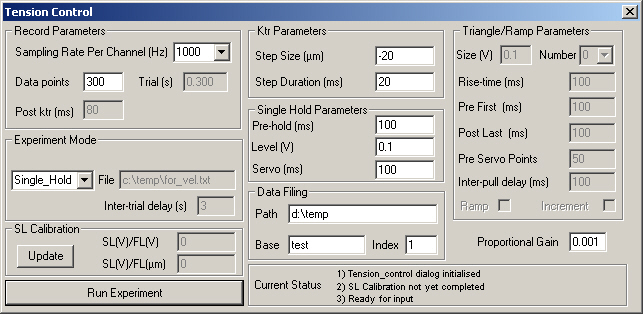
The Tension_control_dialog window opens in the top left corner of the computer screen when the user selects Experiments->Tension control from the main dialog window. The Tension_control_dialog window is an object of class Tension_control_dialog (see the Classes documentation for more information) and automatically opens 2 daughter windows. The first of these (displayed in the bottom left of the screen) is an Experiment_display window. The second (in the top right) is a Calibration window. The Calibration window in turn opens its own daughter window in the bottom right of the screen, Cal_display. Thus opening the Tension_control_dialog creates 4 windows on the computer screen. You can find further information about the controls for these other windows in the appropriate documentation files.
For more information about the Tension_control_dialog controls, scroll down through this page or click on the appropriate control in the screen-shot below.
Explanation
Sampling rate per channel (Hz). User selects appropriate value from drop-down menu. Note that timing of waveforms will only be accurate to the reciprocal of the channel sampling rate. For example, if a record is digitised at 100 Hz, the timing of the output channels will only be accurate to +/- 10 ms.
The number of data points per channel.
The record duration in seconds. This number is the product of the sampling rate per channel (in Hz) and the number of data points per channel. This control is disabled. To adjust the value, the user must change either the sampling rate or the number of data points.
The time interval (ms) after the ktr step is complete. SLControl checks that this value is greater than or equal to zero before running each trial. If not, SLControl aborts the trial before it is initiated and no data record is written to file. The control is always disabled. To adjust the value, the user must change at least one of the other experiment parameters. For example, if the value is negative, the user could increase the number of data points to increase the length of the trial.
The full path for a data file containing experiment parameters for the multiple trial experimental modes (Force-velocity and Batch-pulls). The control is disabled unless one of these modes is selected. The file formats for the two modes are different though each is a simple ASCII text file containing only numbers. The first number in each file is an integer (i.e. no floating point) defining the number of trials to perform. The rest of the file is a list of parameters (all floating point) for each trial. Force-velocity trials are defined by 2 float values. The first is the relative hold level, the second is the relative gain. Batch_pulls are defined by a single value, the inter_pull_interval in ms. Examples of the two formats are shown below.
| Force-velocity | Batch_pulls | ||
| File | Comments | File | Comments |
| 3 1.0 1.0 0.5 0.45 0.12 0.1 |
Number of trials @ 1.0*Isontonic level with gain 1.0*proportional_gain @ 0.5*Isontonic level with gain 0.45*proportional_gain @ 0.12*Isontonic level with gain 0.1*proportional_gain |
3 100.0 10.0 1.0 |
Number of trials Inter-pull interval (ms) 100.0 Inter-pull interval (ms) 10.0 Inter-pull interval (ms) 1.0 |
The time interval (in seconds) between consecutive trials when the multiple trial modes (Force-velocity and Batch-pull) are selected. The control is disabled when SLControl is in single trial mode.
Updates the sarcomere length calibration parameters with the appropriate values from the daughter Calibration window.
A SL calibration factor defined as the measured change in Sarcomere length signal for a unit change in FL_COMMAND volts. This value is derived from SL(V)/FL(Ám) ratio set in the daughter Calibration window and the control is disabled at all times. To update the value, the user must first change the value in the Calibration window and then select the Update button in the Tension_control_dialog window. Although this arrangement may seem unusual, it allows the user to check the calibration factors between experiments without necessarily altering the experimental conditions for the Tension-control experiments.
A SL calibration factor defined as the measured change in sarcomere length signal for a 1 micron increase in FL_COMMAND volts. The value is set in the daughter Calibration window and the control is disabled at all times. To update the value, the user must first change the value in the Calibration window and then select the Update button in the Tension_control_dialog window. Although this arrangement may seem unusual, it allows the user to check the calibration factors between experiments without necessarily altering the experimental conditions for the Tension-control experiments.
As the label suggests, this button initiates an experiment. If the user has selected the Single_Hold or the Single_Pull mode, pressing this button will run a single trial. If the user has selected a multi-trial mode, this button will initiate a train of consecutive trials, separated in time by the Inter-trial-delay. In this case, the number of trials performed depends on the parameters set in the appropriate Batch file.
As the label suggests, this button initiates an experiment. If the user has selected the Single_Hold or the Single_Pull mode, pressing this button will run a single trial. If the user has selected a multi-trial mode, this button will initiate a train of consecutive trials, separated in time by the Inter-trial-delay. In this case, the number of trials performed depends on the parameters set in the appropriate Batch file.
The size of the ktr step in microns. If the user wants to maintain constant tension without imposing a ktr step afterwards, this control can be set to 0. Negative values indicate a shortening step.
The duration of the ktr step in milliseconds.
The length of time (ms) to hold fibre length constant before initiating tension control. This control is disabled if the user has selected a tension-control pull mode.
The desired change from the prevailing level in the measured force signal (in volts) during the tension control portion of the experiment. As an example, if this value is equal to 0.1, SLControl will try to stretch the muscle until the force value has risen by 0.1 V from the prevailing value at the commencement of the tension control phase. Most force-velocity experiments (where the muscle is allowed to shorten under a constant load) will use negative values of level. This control is disabled if the user has selected a tension_control pull mode.
The length of time (ms) for which the fibre is held under constant tension. This control is disabled if the user has selected a tension-control pull mode.
Each data record is automatically written to file once the trial is completed. This section of the dialog box allows the user to define specific filenames. The record filename is composed of three parts: (1) the path e.g. c:\temp, (2) the base e.g. test and (3) the filenumber e.g. 10. In this case, the filename would be "c:\temp\test10.txt". The ".txt" is added automatically. Each time SLControl writes a file successfully, it increments the filenumber by 1, ready for the next record.
The user can overwrite old records by resetting the filenumber. Note however that SLControl will not warn the user if it is about to overwrite an existing file. Although this might seem like a shortcoming, it could create problems if the user was trying to perform multi-trial experiments.
SLControl will warn the user with a MessageBox() if the file cannot be created, an error which woudl result in loss of data.
This section of the screen is used to display information about SLControl's current status for the user. There are no controls for the user to manipulate - you cannot scroll backwards through the status messages for example.
The maximum pull size requested (in volts). This control is disabled unless a tension-control pull mode has been selected.
The number of pulls (either triangles or ramps) requested by the user. This control is disabled unless a tension-control pull mode has been selected.
The rise-time in ms for each pull. This value is equal to the total duration of a single ramp pull, or half the duration of a triangle. The control is disabled unless a tension-control pull mode has been selected.
The time duration in ms before the first tension pull. The control is disabled unless a tension-control pull mode has been selected.
The time duration in ms after the last tension pull and before the ktr step. The time duration in ms before the first tension pull. The control is disabled unless a tension-control pull mode has been selected.
The number of sample points per channel before the tension control servo initiates. This control allows the user to sample a period of the record at constant fibre length (fixed motor position) before tension-control starts. It serves the same purpose as the Pre-hold control for the Single_hold experiment mode. The control is disabled unless a tension-control pull mode has been selected.
The time interval (in ms) between consecutive triangles/ramp pulls. This control is only active if the user has selected a tension-control pull mode and the number of pulls is greater than 1. It is however over-ridden by the parameters in the Batch-file if the user has selected the Batch_pull mode.
Checking this box ensures that SLControl tries to generate a saw-toothed instead of a triangular tension pull. Tension rises linearly to a maximum of Pull-size volts in a time interval of Rise time ms and then falls abruptly to zero. The control is disabled unless a tension-control pull mode has been selected.
This control is only active if the user has selected a tension-control pull mode, the number of pulls is greater than 1 and the ramp mode is selected. Under these conditions, the target tension waveform rises as a series of ramp and holds, each one building on the previous. For example, if there are 3 pulls and Pull-size is 1 volt, the target tension at the end of the third pull will be 3 volts.
This control defines the proportional gain of the tension servo system. If the servo is active, and the desired (target) tension is x volts greater than the measured tension value, the motor command (fibre length) voltage will be decreased by (FL_POLARITY*proportional_gain). Large positive values of proportional_gain speed the system response but can decrease stability (i.e. the motor can oscillate). The motor responds more slowly when proportional_gain has a small positive value but is very unlikely to destabilise.
The best value of proportional_gain will depend on the muscle preparation, the activation level and the type of experiment. It may be helpful to start with very low values of proportional_gain (e.g. 0.001) and slowly increase it in consecutive trials until a suitable system response is obtained.