This basic guide is provided to help new users set up SLControl for their own systems. The instructions are quite simple and do not cover every eventuality. In most cases however, they should be sufficient to enable users to calculate and set calibration values for their specific apparatus.
Before proceeding, it should be noted that it is possible to damage the experimental apparatus during the calibration procedure. For example, if the motor is positioned close to a fixed object (or worse the force transducer!) and a wrongly calibrated command voltage is applied, the motor might move wildly out of control. This obviously has the potential to cause severe damage to the apparatus. These instructions are provided with good intent but no guarantee can be made that are completely foolproof.
SLControl
The first step of the process is to install SLControl.
The current installation package should be downloaded from the downloads section of this site. Installation should be straightforward. In Ver 3.0 and later, SLControl can be installed simply be executing (e.g. double-clicking) the file. The default options should be appropriate for most systems. SLControl will be installed on the host system (by default on the path c:\Program Files\uw_madison\slcontrol) and an icon will be added to the Start menu.
If SLControl is going to be used solely to analyse data files recorded on another system, this is the only stage of the process which needs to be completed. If on the other hand, SLControl is going to be used to record experiments, a DAP board needs to be installed on the host system and the apparatus calibration values must be set appropriately.
DAP board
SLControl runs experiments using a DAP (Data Acquisition Processor - a 5216a device in the original configuration) from Microstar Laboratories. SLControl assumes that the device and the accompanying Accel32 server have been correctly installed. The CD which Microstar ships with each board contains detailed instructions on how to proceed. Questions about this stage of the process should be directed to Microstar Laboratories.
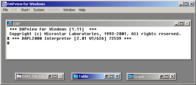
The simplest way of checking that the board and server are working correctly is to start DapView for Windows (also included on the Microstar CD). The "Dap" window (which echoes commands to the processor) should look similar to the window below though the last number on the third line (the DAP serial number) will be different. If the user types "Hello" followed by Return, the DAP should repeat the status line. If everything seems to be working proceed to the next step. If not, check the installation of the DAP and Accel32.
Connections
SLControl assumes that specific signals to/from the apparatus are connected to designated input and output channels of the DAP. These channel connections are 'hard-wired' in the SLControl source code and can not be changed. Full details are provided in the DAPL connections file.
Please note that this is a crucial stage of the installation. If the experimental apparatus is wrongly connected, SLControl cannot operate correctly and the experimental apparatus may be damaged.
Calibration parameters
The final (and most involved) stage of the installation is to set the apparatus calibration parameters. These are fully described in the Calibration_parameters file. This guide indicates one way of establishing their correct values.
The first thing to do is to establish the correct value of FL_POLARITY. This parameter determines which way SLControl should adjust the motor command voltage to lengthen the muscle and should only be set to +1.0 or -1.0.
Move the motor away from any potential obstruction, switch it on, and start SLControl. Select the SL_SREC experiment mode (Experiments->SL_SREC), adjust the ktr step duration to 800 ms. All other parameters should remain at their default values - in particular the ktr step size should be a negative value (SLControl asssumes that negative values correspond to muscle shortening). Look carefully at the motor and press "Run Experiment". The motor should stay at its initial position for 100 ms, step to a new position for 800 ms and then return to its starting point. Check carefully to see which way it moves during the step.
If you can't see any movement, increase the ktr step size (say to -40 µm) and run the experiment again. Keep increasing the step size gradually until you can see a movement and you are sure which way the motor is moving during the step. If the motor moves in the direction which would shorten muscle length in your system, FL_POLARITY is set correctly. If on the other hand, the motor would stretch a muscle during the step, FL_POLARITY is wrong. Close SLControl, open the calibration parameters file in a text editor, change the value of FL_POLARITY (i.e. if it was -1.0, change it to +1.0 and vice versa). Save and close the file and restart SLControl.
Once you have satisfied yourself that negative values of ktr step size correspond to muscle shortening, you can proceed with the next stage of the calibration.
At this point, the motor is still not calibrated correctly. Now that FL_POLARITY is set correctly, SLControl should move the motor in the right direction, but the size of the movement will almost certainly be wrong. If the ktr step size is set to -100 µm, the motor will shorten the muscle but it might do so by more or less than 100 µm depending on the motor and the length of the arm. The next stage of the installation procedure is to set the motor calibration values.
To proceed with this stage of the installation, you need some way of precisely measuring the movement of the motor, and of measuring two voltage signals - the motor command voltage (i.e. the signal which is passed to the motor system) and the motor response voltage (i.e. the signal coming back from the motor indicating its position). By far the easiest way of measuring the voltages is to use a two-channel oscilloscope. If you don't have access to one of these, the operation is a bit more complicated, but there is a work-around through SLControl.
How you are going to measure the position of the motor depends on your system. If your apparatus is built on an inverted microscope, it should be fairly straightforward. Simply measure the motor movement on your calibrated TV screen or eye-piece. If you can't visualize the motor itself, you will have to be more creative. One way of proceeding is to project an image of the motor through a camera lens onto a distant screen and calibrate the image size with an object of known dimensions positioned next to the motor.
Motor calibration using an oscilloscope
Use T-pieces and extra BNC cables to connect copies of the motor command voltage (output from DAC1) and motor response voltage (input to S2) to the two channels of your oscilloscope. Start SLControl and select System Checks->Square wave FL. Pressing Start will pass a square wave command to the motor which should step back and forth between two fixed positions. If the movement is too small to visualize, press Stop, increase the Square wave half-height and press Start again. You may find it easier to measure the movement if you slow the square wave down by increasing the half-period time.
The aim of this stage of the calibration is to measure the changes in the motor command (Puller In on Aurora/Cambridge systems) and response (Puller Out) voltages and plot them against the measured displacement of the motor. By repeating the measurements with different step-sizes, you can create graphs similar to those shown below.
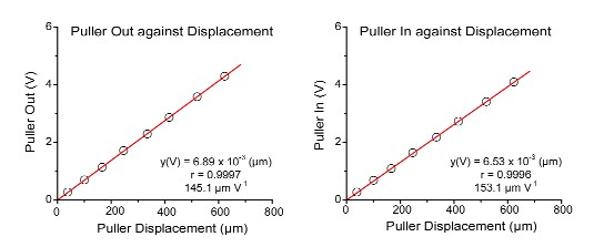
The gradients of the best-fit lines are indicative of the motor calibration values. In some cases (for example, the old Cambridge motors, Model 6350's), the two gradients will be approximately equal. This indicates that the motor response voltage changes approximately equally with the motor command voltage. In other cases (for example, the Aurora 308 series), the two gradients will be different. If the Puller In voltage on an Aurora 308 series changes by 1 V, the response changes by about 500 mV. The newer Aurora motors (e.g. 312B) have switchable gains. In this case, the ratio of the gradients will depend on the gain factor selected.
SLControl's motor calibration values are expressed in units of µm V-1 i.e. how far the motor moves in microns for a one volt change in voltage. In the example above, the FL_RESPONSE calibration factor (calculated from the puller out graph) should be 145.1 µm V-1. The FL_COMMAND calibration is 153.1 µm V-1. Close SLControl, open the calibration parameters file in a text editor, set the new calibration values and save and close the file. Restart SLControl. You should see the new calibration values in the initial dialog box.
Motor calibration without an oscilloscope
The calibration procedure without an oscilloscope is basically similar to that outlined above, except that you will need to use SLControl to produce and measure the length change. You can do this by temporarily connecting a copy of the FL_COMMAND voltage (Puller In) to the SL input (S1 on the DAP). (Remember to reconnect the sarcomere length signal afterwards.) Then use the SL_SREC control panel to impose long length steps (as you did when setting FL_POLARITY). The FL_RESPONSE voltage signals (Puller Out) and FL_COMMAND (Puller In) will be shown in the Experiment_display window as FL and SL respectively.
Measure the sizes of the two voltage steps and note the distance the motor moves. Repeat this process with both positive and negative values of ktr step size (so that the calibration is centered around the motor's null position) until you can re-create the graphs shown above.
Verification of motor calibration
At this stage, you should probably check that the parameter values are set appropriately. Select the SL_SREC experiment mode (Experiments->SL_SREC) and set the ktr step-size to a value which is large enough for you to visualize. Increase the duration of the ktr step so that you can measure the magnitude of the motor movement before the motor steps back. You might want to adjust the data record length (either by increasing the number of data points, or by lowering the sampling rate) to help with this. Then press "Run Experiment". The motor should step and the experimental record should be displayed in the Experiment_display window in the bottom left-hand corner. Repeat this experiment until you are happy that the motor has actually stepped the appropriate distance (i.e. the measured motor displacement from your microscope/projection system etc. is the same as the desired value.) If so, the FL_COMMAND calibration factor has been set correctly.
You should now check the FL_RESPONSE factor. Open the last data file (Analysis->Single Data File) and select Transform->Change to Calibrated Values from the Analysis_display menu. The fibre length signal should now be displayed in meters. The initial value will be wrong (it is set equal to the fibre length in the Calibration window and should have defaulted to 999 µm), but the magnitude of the ktr step should be equal to the ktr step-size set during the test. If so, you have also set the FL_RESPONSE calibration factor correctly as well. If not, you will have to go back and repeat the calibration procedures again, checking carefully for arithmetical slips, or measurement errors.
Force calibration
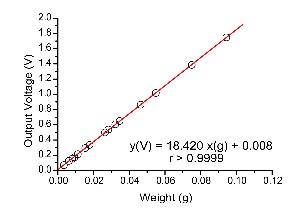
The final stage of the calibration procedure is to set the FORCE_CALIBRATION factor. This value is the increase in measured force (in Newtons) when the force input voltage increases by 1 volt. In the example below, the calibration factor can be determined from the gradient of the regression line, but it must be correctly expressed in units of N V-1 (in this case, 5.326e-4). If you happen to have a force transducer where the output voltage decreases with increasing force, the calibration factor should be negative. Close SLControl, set the appropriate factor in the calibration parameters file and restart SLControl.
You may want to check this value by unloading the transducer by a known amount (e.g. position the force transducer vertically and unhook a weight?) during a data record. Open the data file (Analysis->Single Data File), Transform to calibrated values and check that the force record is correct. i.e. if you unhooked a weight of 0.01 g, you should measure a force change on the data record of about 1e-4 N. Note though that the calibrated values are expressed in N m-2 so that they correct for the cross-sectional area of the muscle. To get 1e-4 N, you will have to multiply the measured tension change in N m-2 by the cross-sectional area of the preparation. The default value is 999.0 m-2. It should be displayed in the bottom right hand corner of the Analysis display window.
Summary
That's it. SLControl should now be correctly calibrated. You have checked that the motor moves the appropriate distance in the correct direction during an experiment and moreover is reported as having done so. You've also set the appropriate force calibration factor and checked that force values are recorded correctly as well. Hopefully you will also feel confident that you can perform simple ktr experiments as well. Sarcomere length and tension control will come with practise...
Happy experimenting,
![]()