This document is intended to help new users perform their first experiments under Tension control. The instructions have been kept as simple as possible, and the guide does not cover every eventuality. If you have suggestions on how to improve the guide for other users, please get in touch.
This guide also assumes that SLControl has been correctly installed on your system and that the apparatus calibration parameters have been set correctly. If not (or if you are not sure!) please refer to the Getting started tutorial before proceeding further.
IMPORTANT NOTE
This guide assumes that the force transducer has a positive calibration factor i.e. if the measured force increases, so does the output voltage. If this isn't the case in your particular system, you should be careful to adjust the polarity of the level voltage appropriately.
Overview
SLControl's implementation of tension control is strightforward. One end of the muscle is attached to a force transducer which measures the tension in the preparation. The other end of the muscle is attached to an actuator (normally some sort of motor) which can be used to change the preparation's length. When the tension servo is operating, the DAP simply compares the measured force value to a target level which was pre-calculated before the recording initiated. If the measured value exceeds the target, the muscle is shortened. If the measured value is less than the target, the muscle is lengthened.
Although the underlying principle is straightforward, tension control is in practice rather difficult to implement. The main problem is that there is no straightforward relationship between actuator position and muscle force. The implication of this is that there is no one value of servo gain which produces adequate tension control in different types of experiment. Instead the gain factor (i.e. the ratio defining the extent of actuator movement for a given difference between the measured and the desired force values) must be adjusted between experiments to produce optimal results. In effect, SLControl's servo system needs to be 'tuned' for each experiment.
This tutorial describes some simple tests which are designed to acquaint new users with tension control measurements. The aim is not to explain how individuals will perform their own specific experiments but rather to provide them with an opportunity to gain confidence and experience of the general technique. As ever, if you have specific questions, please feel free to ask for further advice.
Test measurements
Getting optimal performance in tension control experiments takes a little practice. In particular, if you set the gain of the servo system too high, the motor position may oscillate rapidly, potentially causing damage to the experimental apparatus. We recommend that you try your test measurements with some sort of thread or elastic band taking the place of the muscle. This has two advantages. First you don't waste time preparing a biological preparation. Second you can the make the thread long enough that the motor won't hit the force transducer if it starts to oscillate.
The measurements described here were obtained with a single strand of dental floss about 1 mm long tied between the motor and the force transducer. The thread is quite a lot stiffer than a muscle fiber (and it doesn't have a hyperbolic force-velocity relationship!) but that doesn't really matter since all we're trying to do in this tutorial is get the hang of how the system works.
Tension control dialog
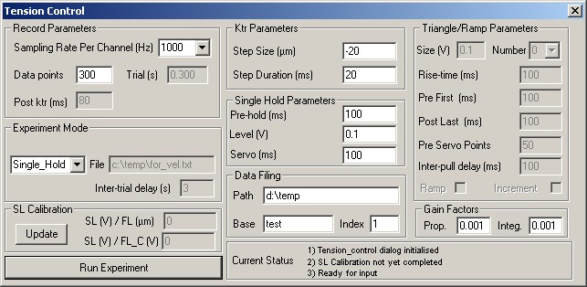
The first step in performing a tension control experiment is to open the appropriate Windows dialog using the menu at the top of the main screen (Experiment->Tension Control). You shold now see 4 windows, the top left of which looks like the one below. If you want more information on the individual controls, check the Tension control page in the Interface section.
Pressing the 'Run Experiment' button (don't do it just yet!) will initiate an experiment similar to that shown in schematic form below.
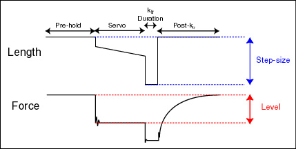
The first phase of the record is termed 'Pre-hold'. The tension servo is off and the motor is simply held at its default (null) position. Looking at the dialog (middle column), you'll see that the default length of this phase - Pre-hold (ms) - is 100 ms.
The next phase of the record is 'Servo'. The tension servo will be on and the system will be trying to move the motor so that the measured force is 'level' volts above the prevailing level at the end of 'Pre-hold'. The default duration of this phase is also 100 ms. The default setting for 'level' is 0.1 V i.e. the motor will move away from the force transducer trying to stretch the thread so that there is an extra 0.1 V of measured tension. (Note in the figure above, tension actually drops during the servo phase. We'll do this in our experiment by setting 'level' to a negative value.)
The last two phases are straightforward. During the ktr phase, the muscle is shortened by 'Step size (�m)' from its initial length (not from the length at the end of the servo phase!) and held at that short length for 'Step duration (ms)'. The default values are -20 �m (negative numbers denoting shortening) and 20 ms respectively. Thereafter the muscle is rapidly re-extended to its default length and held there for the duration of the record. There are no specific parameters for this phase but you can tell the implied duration from the box labelled 'Post ktr (ms)' (top left of the dialog). To change this value, you have to change the sampling rate or the total number of data points in the record.
Let's try and make the experiment a bit more like the sort of thing you might want to try with a muscle. First of all carefully move the motor or the force transducer so that there's some standing tension in the thread (say about 500 mV). You might want to adjust the size of the ktr step to help with this. Then change the value of level to -0.2 V. This will ensure that the motor is going to shorten the thread (to drop the measured force) during the servo duration (though check the note at the beginning of this tutorial if you have a negative force calibration factor). You may also want to change the default file-name and directory path for the recorded data file if it's not appropriate for your system. Finally and most importantly, set the 'Prop' (proportional) and 'Integ' (integral) gain factors to zero. These dictate how far the motor will move during the servo phase. Setting them to zero will prevent the motor from moving at all.
Once you have made these changes, 'Run' the experiment. If everything has gone according to plan, you should have recorded 300 ms of stable force and motor position data (like Panel A in the figure below, but note that the timing is a little different in these examples). The ringing on the force record before and after the ktr step in the figure are the lightly damped oscillations of the thread and force transducer.
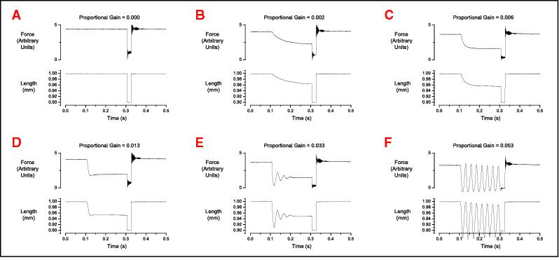
Now try increasing the proportional gain from 0 to 0.0001 and run the experiment again. If you don't see any changes, gradually increase the proportional gain until the motor starts to move. The actual values you're going to need are impossible to predict because they depend on the parameters of your setup and the stiffness of the thread etc. but the general advice is be cautious. Try incrementing the gain in steps of 0.0001 or 0.0002 until you get the hang of things. Also don't try fiddling with the integral gain at this stage - leave it at zero.
Panel B is an example of an experiment where the proportional gain is just high enough that the motor is starting to move. Note though that the motor response is fairly slow and that the force never really settles down. As the proportional gain is gradually increased (Panel C) the system gets a little faster and the force is tracked a little better. Panel D represents a near optimal response for this particular setup. Force drops quite quickly and is held at a fairly steady level after about 20 ms or so. In E and F, the proportional gain is too high and the force record oscillates at the beginning of the step. The higher the gain, the more it oscillates. If the gain is much too high (higher than shown here) the motor may move wildly out of control. This happens when the feedback correction is so large that the motor moves further away from the desired position than it was before the correction was imposed.
When you feel you've got the hang of tuning the proportional gain, you might want to experiment with different sampling rates. The system can update the motor command signal at up to 5 kHz. Note though that the specific gain values will be different for different sampling rates. Generally, the higher the update rate, the lower the required gain because the corrective movements are being applied more frequently.
You may also find that you can improve the system's step response by adding a small amount of integral gain. This works by adding an additional correction term which is based on the cummulative difference between the measured and the desired force signals. In some circumstances, this can make the step quicker and more stable. In others (particularly at high sampling rates), it can make things worse. As ever, the best thing to do is to see what works best in your particular situation.
Summary
Hopefully working through these simple measurements will have taught you how SLControl implements tension control protocols. With luck you'll feel ready to try it with real muscle fibers. As ever, if you have questions or want further information, please get in touch.
Happy experimenting,
![]()