Water Distribution
System Toolkit
Hardware: Sensor and SCADA
A water distribution system is made up of many different operational components, including sensors, meters, pumps, and control valves. Components can be monitored or controlled onsite or from a central location. In the past these operations were normally accomplished through the use of onsite instrument and control panels. These panels typically consist of a series of electro mechanical devices such as indicators, push buttons, lights switches, relays and analog control instruments. In recent years many utilities have made the transition to computerized Supervisory Control and Data Acquisition (SCADA) systems in which commands are entered through a keyboard, mouse, or touch screen instead of through the use of switches or push buttons.
Potential SCADA Uses
A SCADA system is a widely distributed computerized system primarily used to remotely control and monitor the condition of field-based assets from a central location. Field-based assets include wells, pump stations, valves, treatment plants, tanks, and reservoirs (Bentley, 2004).
Generic uses of SCADA in distribution systems include:
-
Security monitoring
-
Energy management
-
Monitor equipment operations to forecast maintenance, repair, and replacement
-
Sub-metering utility usage
-
Identifying alarm conditions
For water distribution, the operational and managerial uses of a SCADA system include the following:
-
Monitor the system
-
Exercise control over the system and ensure that required performance is continuously achieved
-
Reduce operational staffing levels through automation or by operating the system from a central location
-
Monitor and store data of a system’s behavior, and use the data to achieve full compliance with regulatory reporting requirements
-
Obtain information on the performance of the system and establish effective asset management procedures for the system
-
Establish efficient operation of the system by minimizing the need for routine visits to remote sites.
-
Potentially reduce power consumption during pumping operations through operational optimization
-
Provide a control system that will enable operating objectives to be set and achieved
-
Provide an alarm system that will allow faults to be diagnosed from a central location, thus allowing field repair trips to be made by suitably qualified staff to correct the given fault condition and to avoid incidents that may be damaging to the environment.
-
Monitor system operations to identify excursions of operating equipment from normal operating conditions/ranges.
-
Monitor equipment operations to forecast maintenance, repair and replacement.
-
Use SCADA data to verify hydraulic and water quality models.
-
Use SCADA data to identify intrusions, leakages, and other variations from normal system, operations.
-
Use of SCADA in support of real-time modeling
SCADA in Support of Energy Management
One of the most effective uses of SCADA systems is in managing the energy usage of the water pumping and distribution systems. For additional ways to use SCADA data in improving the energy efficiency of such systems check out the additional information below:
Energy Efficiency of Water Distribution Systems
SCADA Functions
SCADA Function categories are:
-
Data Acquisition (Collection)
-
Data Communication (Monitoring)
-
Data Presentation
-
Equipment Control
Note that these SCADA function categories are in a specific order; in other words the second, third and fourth functions all build on the prior functions, The first three SCADA function categories deal with data acquisition. Many water systems, especially smaller systems, do not elect to use supervisory control aspects the SCADA in the daily management of their system. All SCADA systems must have data acquisition and communication before any supervisory controls can be implemented; therefore, many industry professionals believe that the “DA” of SCADA, or data acquisition portion of SCADA, is the most important part of the system. Closely tied to the data acquisition, is the communications and data logging/presentation aspects to the SCADA
SCADA Survey
As part of this research effort, 22 utilities were surveyed with regard to their use of SCADA. Additional information about the survey can be obtained below:
SCADA Components
All of the SCADA Functions are carried out by SCADA Equipment. There are four SCADA equipment categories that are illustrated in Figure 1 below.
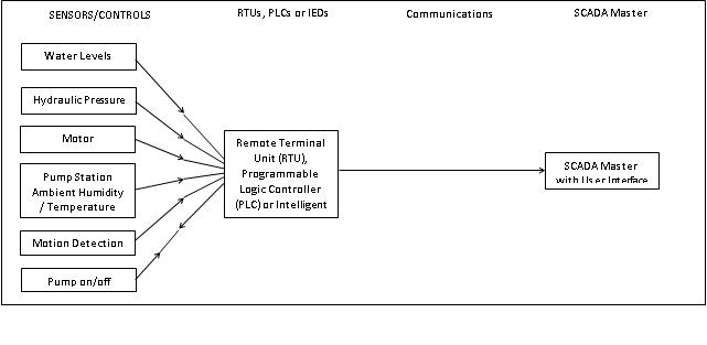
Figure 1: Illustration of four SCADA Equipment Categories
1. Sensors and Controllers - Sensors (either digital or analog) and control relays directly interface with the managed system. Additional information on both types of components can be found below:
2. SCADA Interface Units - Most SCADA systems associated with water distribution systems typically employ one or more types of SCADA interface units. These include: the remote terminal unit (RTU), the programmable logic controller (PLC), or the intelligent end device (IED). Remote Terminal Units (RTUs), Programmable Logic Controllers (PLCs), and Intelligent End Devices (IEDs) are small computerized units deployed in the field at the specific sites and locations where sensors and equipment controllers are utilized. RTUs, PLCs, and IEDs serve as local collection points for gathering status from sensors and delivering commands to control relays. More information on each of these components can be found below:
3. Communications Network-the communication network is used to connect the control master of the SCADA system to the SCADA interface units. There are two primary types of systems to consider when designing telemetry and communication systems. In a uni-directional system, remote terminal units report data to a central location, but do not accept remote command and control instructions. Remote telemetry is truly bi-directional in nature, reporting both statistics and accepting instructions from a central computer or controller. In most cases, it is worth remembering that in a uni-directional system, terminal units only send data, the managing system requires a bi-directional link; the link itself can usually both send and receive information.
4. SCADA Master - These are larger computer consoles that serve as the central processor for the SCADA system. Master units provide a human interface to the system and automatically regulate the managed system in response to sensor inputs.
Supervisory Control Schemes
SCADA systems are usually built around a central computer and operator’s station, which communicate with intelligent Remote Terminal Units (RTUs) or Programmable Logic Controllers (PLCs) via an integrated communication network. The exact composition of the system will be dependent upon the selected control scheme. Two different control schemes are available: hierarchical control or distributed control (Clingenpeel and Rice, 1990).
Hierarchical Control
In a hierarchical control environment there is normally a single control computer which is linked to several remote control units via the communication network. RTUs are normally used for the remote control units. Each RTU contains a point database for all field I/O points and calculated values like flow totals, tank volumes, etc. The central computer contains a mirror image database which includes points for all RTUs in the systems. Under normal operation the RTU continuously scans all input points and updates the calculated values. The central computer is then used to poll each RTU to update the central database. Any control decisions are then sent back to the selected RTU for control of a particular network component (Riddle, 1989).
Distributed Control
In a distributed control environment more of the control is distributed to the remote stations. Although a distributed control system can also contain a central host computer, it is typically used more to manage and monitor the control units as opposed to controlling the actual field instrumentation. PLCs are normally used as the control units for this type of system. Since the PLCs are connected to a central host computer, the computer can still be used to monitor all the control data. However, in this case the central computer can be used to change selected set points of the associated remote control units or even download complete control schemes (Christie, 1989).
Advantages and Disadvantages
The principal advantage of the hierarchical approach as opposed to the distributed approach is the lower cost of the system. This is primarily due to the cost of the RTUs as compared to the PLCs. The chief disadvantage of the hierarchical approach is the inability of the system to operate in the event of a failure of the communication network. Other problems can arise due to differences in the telemetry data transmission rate and the computer scan rate (Clingenpeel and Rice, 1990).
The primary advantage of the distributed approach is that normal operations can still be maintained despite a loss of the telemetry link or even the central computer. In addition, since the control hardware is located at the control point, potential differences in the transmission and scan rates can be more readily minimized (Clingenpeel and Rice, 1990).
SCADA Sensor Location
One of the critical elements in designing a SCADA system is to know where to place the various sensors that will supply critical information to the system. Determining locations where either hydraulic or water quality sensors should be installed should be driven by exactly what information is needed about the distribution system. For example, if all that is needed is the water level in an elevated storage tank, then obviously placing a pressure sensor at or near the base of the tower is probably the logical choice. However, the placement choices become very complicated when the most logical option is not economical or a physically optimal option. The remoteness of the location and access to such facilities sometimes pose questions that are hard to answer. The use of computer modeling for sensor placement is increasing. The USEPA model Threat Ensemble Vulnerability Assessment-Sensor Placement Optimization Tool (TEVA-SPOT) is one such computer tool available to assist in sensor location decisions. Hart and Murray (2010) reported on three sensor placement strategies that are being applied for deployment of DWS: expert opinion, ranking methods, and optimization (computer modeling). Berry, et al, (2005) reports that tests of the use of sensor placement modeling and the decisions made by local experts in a water supply system "... suggest that a collaboration between modelers and those with practical water system expertise can improve the effectiveness of sensor placement decisions”. Programs like TEVA-SPOT can assist in finding optimal locations for each sensor in a distribution system for use as a component of a drinking water system, while the operators and/or managers need to decide which among the potential alternative locations are optimal to place the sensor for their purposes.
The placement choices can become very complicated if the purpose of the sensor is to determine model inputs for a hydraulic model, or if the goal is to monitor for maliciously injected contaminant, which is termed a contaminant warning system (CWS), or detect pipe bursts and other leakage. (Mounce, S. et. al., 2003 and 2006), (Berry, J. et. al., 2005) Hydraulic sensors are very useful for modeling water quality in a distribution system, by monitoring flows, and thus residence times in the system. This use of hydraulic data also has direct application to regulatory compliance.
Berry, J, et al (2005) identified placement cost budget, contamination public health impacts, and potential attack scenarios as considerations in sensor placement. The Public Health Security and Bioterrorism Preparedness and Response Act of 2002 identified physical security of water supply distribution systems as a major priority for water utilities. So, in addition to combining hydraulic and water quality sensors in the same location, consideration of the value of data from these sensors at locations of security sensing (e.g. water storage towers, basins, and pump stations) may be worthwhile.
SCADA sensor placement decisions made without the use of computer models are frequently based on the experience of the decision-maker and his/her support group’s experiences. Following is a list of sensor placement design issues provided in a sequence used by the authors (Mounce, S. et. al., 2003 and 2006), (Berry, J. et. al., 2005) in the design of SCADA systems.
SCADA Sensor Placement Decision-Making Sequence
-
Determine intended uses of data
- hydraulic and water quality monitoring
- security monitoring
- energy management
- equipment management including repair and replacement forecasting
- sub-metering utility usage
- identifying alarm conditions
- verifying hydraulic or water quality modeling
- provide data as a component of a CWS
-
Determine parameters of interest to be monitored
-
Determine locations/areas for which data are desired
- areas or location of major public health impacts from contamination (schools, health care facilities, food preparation, elderly living centers, etc.)
- potential contamination attack scenarios and locations based on physical characteristics of distribution system
- areas of known poor water quality in distribution system based on complaints,
- locations of regulatory agency required compliance sampling
-
Determine locations of other types of sensors currently in distribution system
-
Determine potential locations of other (security, water quality, etc.) sensors to be added to the system
-
Determine potential locations based on the above
-
Determine security & accessibility of potential sensor sites
-
Determine cost components (relative costs) by location
-
Determine sensor station design & construction budget available
-
Determine final sensor placement locations
SCADA CWS Sensor Placement Optimization Program Inputs
Sensor placement computer programs (e.g., TEVA SPOT) are available to optimize the locations of the sensors to minimize the impacts of a contamination incident. To use one of these programs, complete, accurate and calibrated hydraulic and water quality models of the distribution system are necessary to provide inputs to the sensor placement program. Following is a list of the information/data needed from the system operators and/or managers for input to these programs.
-
Complete and calibrated hydraulic and water quality distribution system models.
-
Simulation time - the length of time (number of hours) the program run should simulate.
-
Time of release - the length of time a contaminant is injected into the distribution system.
-
Mass injection rate (mg/min) - the amount of contaminant that is injected into the distribution system per unit time.
-
Contaminant - the contaminant(s) that may be injected into the system.
-
Response time delay - the time between initial detection of a contaminant in the distribution system and when public warnings are issued.
-
Detection limit - some level of contaminant concentration below the health impact level of an injected contaminant; this must be in the range between the upper and lower detection limits of the sensors.
-
Impact metrics - any of a variety of impacts can be used: the number of people ingesting the contaminant, length of distribution system piping that is contaminated, number of people with health effects from the contaminant.
-
Sensor placement objective - any of a variety of objectives for the placement of sensors can be used: minimize the number of public health impacts, minimize the extent of distribution system contamination.
SCADA Sensor Placement Guidance
As part of the current research program, general guidelines for the placement of SCADA sensors have been developed for use by small utilities. These guidelines can be obtained here:
A Simple Graphical Procedure for Sensor Placement Guidance for Small Utilities
An Advanced Graphical Procedure for Sensor Placement Guidance for Small Utilities
SCADA Sensor Placement Software
Due to the complexity and challenges in applying TEVA-SPOT, researchers at the University of Kentucky have partnered with KYPIPE to develop a simplified sensor placement computer program that can be used directly within the KYPIPE graphical user interface for small utilities. The user's manual and software can be obtained below.
Instructions for Using KYPIPE WQSensor
SCADA System Implementation Process
When considering a SCADA system, there are traditionally two methods that are utilized for implementation. These methods are:
EFI (Engineer, Furnish and Install) Method
References
Bentley Systems Incorporated. (2004). “The Fundamentals of SCADA - A White Paper from Bentley Systems, Inc.
Berry, J., et al. (2005). "Water Quality Sensor Placement in Water Networks with Budget Constraints." Proceedings of the World Water and Environmental Resources Conference.
Berry, J.W., Fleischer, L., Hart, W.E., Phillips, C.A., Watson, J.P. (2005). “Sensor placement in municipal water networks.” Journal of Water Resources Planning and Management, ASCE 131 (3), 237-243.
Berry, Jonathan W., et al. (2005). "Sensor Placement in Municipal Water Networks." Journal of Water Resources Planning and Management, ASCE 131.3: 237-243.
Christie, L.D. (1989). “Understanding Computer Control Options for Water Resources.” Proceedings of the 16th Annual Conference of the ASCE Water Resources Planning and Management Division. Sacramento, CA: pp. 520-523.
Clingenpeel, William H., and Don B. Rice. (1990). "Development of a Water and Wastewater SCADA System." Public Works, 121.7: 60-62.
Hart, W., and Murray, W. (2010). “Review of Sensor Placement Strategies for Contaminant Warning Systems in Drinking Water Distribution Systems.” Journal of Water Resources Planning and Management,ASCE136(6): 611-619.
Mounce, S. R., and Machell, J. (2006). “Burst detection using hydraulic data from water distribution systems with artificial neural networks.” Urban Water Journal, 3(1): 21-31.
Mounce, S., Khan, A., Wood, A., Day, A., Widdop, P., and Machell, J. (2003). “Sensor-fusion of hydraulic data for burst detection and location in a treated water distribution system.” Information Fusion, 4(3): 217-229.
Nollet, M. (1986). “PLC Programming Languages: A Comparison.” I & CS Industrial and Process Control Magazine, 59(3):57.
Riddle, W.F. (1989). “Water Distribution Control: Reviewing Current Practice.” Proceedings of the 16th Annual Conference of the ASCE Water Resources Planning and Management Division. Sacramento, CA: pp. 512-515.
Ritchie, E. (2011). “The New Face of SCADA."Water Efficiency Vol. 6, No. 3: 28-33.